Hillco Technologies

How to Install the Hillco Pivoting Spout: A Step-by-Step Guide for John Deere Combines

Hillco Pivoting Spout, pivot spout, hillco spout, john deere spout

If you’re looking to improve your grain unloading precision and reduce spillage during harvest, the Hillco Pivoting Spout is a smart upgrade for your John Deere combine. This simple-yet-effective attachment enhances unloading control by giving operators up to 37° of directional grain flow adjustment, all controlled with a convenient in-cab foot switch.

In this post, we’ll walk you through the highlights of installing the Hillco Pivoting Spout on your combine—drawing directly from Hillco’s official installation guide for Model JPS1720. Whether you’re retrofitting for the first time or upgrading from a standard auger tip, this guide will help you get set up with confidence.

But First, Tools

Before installation, gather the included parts and these tools:

  • Socket set and wrenches
  • Drill with a 3/8″ bit
  • Zip ties
  • Ratchet straps (recommended for temporary support)
  • Channel locks (to pull tabs together)

Step-by-Step

  • Remove Existing Hardware
  • Remove and discard the existing auger spout tip (A).
  • Either slide back or remove the light strap (C).
  • Remove carriage bolts around the auger tube top (D) and replace grain saver bolts (E) with M8x16 carriage bolts from Bolt Bag 4.
  • Drill a hole using a 3/8″ bit in the designated spot if needed (F) for locating the pivot mount​


🔧 Tip: On some models, drilling may be required to fit the mount properly.

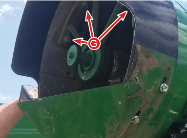
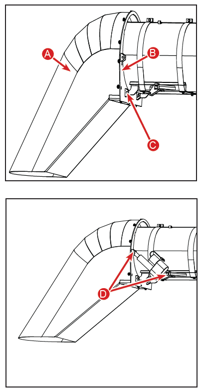
  • Flip the carrier bearing support bolts so the heads face outward (G) for clearance.
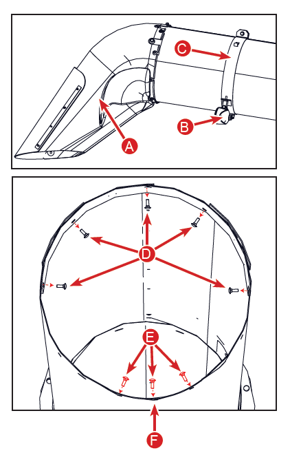
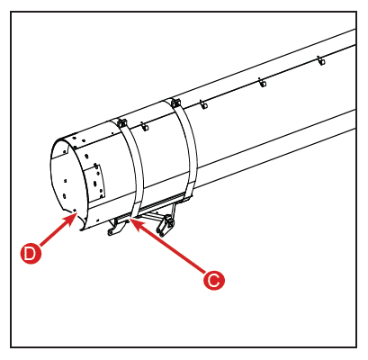
  • Attach the bottom mount (C) over the grain saver bolt and reuse the original nut (D).
  • Pre-attach mounting straps using M8x16 bolts and M8 nuts from Bolt Bag 4 (B).
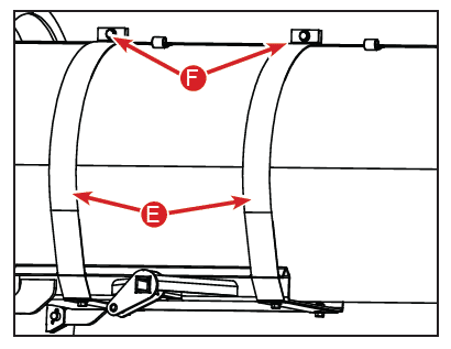
  • Temporarily support the mount with ratchet straps and then secure mounting straps over the auger tube using M8x40 bolts and flange nuts from Bolt Bag 2 (F).
  • Secure the molded spout tip (A) to the ring (B) using M8x25 carriage bolts, washers, and nuts from Bolt Bag 1.
  • Slide the spout into the mount and install clevis pins and cotter keys (C) (from Bolt Bag 3).
  • Attach the actuator (D) using supplied pins.
  • Remount the auger light (E) using pre-drilled holes near the actuator​.

4. Wiring the Pivoting Spout

  • Plug actuator harness 1346681 into the actuator and route it along the auger tube using zip ties.
  • Mount the reverse polarity actuator control box 155853 above the battery compartment.
  • Wire connections:
    • White and black wires to the two bottom terminals.
    • Red jumper wire 1349831 from (+) battery post to the middle spade terminal​.
  • Route harness 1349881 from the controller through the floor near the steering column.
  • Use the provided Velcro tape to mount the foot switch where you can operate it easily with your left foot.
  • Connect the foot switch to harness 1349881.

6. Connect Power Harness

  • Use power harness 1346671:
    • Connect orange wire with 20A fuse to the positive terminal.
    • Connect black wire to the negative terminal.
    • Secure the ground wire to an exposed bolt — not under the cap — to ensure proper disconnect functionality.
  • Be sure the 20-amp fuse is as close to the battery as possible for protection.
  • Use channel locks to help align the spout mount tabs when inserting bolts.
  • Make sure there is enough wire slack for turret rotation to avoid binding when the auger swings.

Troubleshooting at a Glance

  • Spout not moving?
      • Check for a blown fuse or a pinched wire.
  • Spout pivots the wrong direction?
      • Reverse the actuator wires or foot switch wires.
  • Foot switch doesn’t respond?
      • Inspect the switch, verify wire positions, or contact Hillco for a replacement​.

Hit a Snag?

The Hillco team is available if you hit a snag during installation. Reach out at 800-937-2461
Facebook
Twitter
LinkedIn
Shopping Cart
Scroll to Top
close-roi-calculator
Return on Investment Calculator

This calculator is designed to determine the return on investment for a Hillco leveling system equipped combine versus a non-leveling combine operating in sloping conditions.

Acreage Information

Crop Information

Enter your operation's statistics and estimates.
Wheat
Corn
Soybeans

Acreage / Slope Information

Estimate the percentage of total harvested acres that lay within the various slope ranges in your farming operation.
For all Wheat Acreage
See Slope reference chart
Percentage slope values must equal 100%
100%
Your Harvest Speeds and Machine Harvested Yield (MHY)

Non-Leveling Ground Speed in MPH

Enter the average harvesting speed for your non-leveling combine in the various slope ranges at the average yield entered in the Crop Information section above.

Slope Reference Graph
Wheat
Corn
Soy

Reduction in Machine Harvested Yield (bu/acre)

Estimate the reduction of Machine Harvested Yield (MHY) for each slope range if you were harvesting at the speed you entered for 0-3% slopes. (The calcultor will then project expected reductions in MHY for each slope range at your previously estimated ground speeds.)

You may opt to enter the test data which was determined by actual field testing by Hillco (based on 5 mph harvesting speed).

Reduction in MHY is used in these calculations rather than field loss. Reduction in MHY is a more accurate guage of combine harvesting efficiency because it can be determined by actually weighing the harvested yield rather than estimating the amount of yield lost to the ground.

Use test data or your own
Corn
Soy
Your Combine and Header Information
Enter your expected combine harvesting efficiency. Typically a combine operates at approximately 70% efficiency. If the Total Annual Separator Hours calculated below look too small you may want to decrease the combine efficiency. If the Total Annual Separator Hours calculated below look too large you may want to increase the combine efficiency.
Wheat head width in feet
Corn head width in feet
Flex header width in feet
Combine Field Efficiency (Typically 70%)
(Must enter value other than 0%)
Your Operational Costs
This total should include additional cost of benefits and taxes. If you wish to include the grain cart operator's cost add the hourly wage to the combine operator hourly labor costs.
Combine Operator Labor Cost (per hour, including taxes and benefits)
Combine Fuel Cost

If you wish to include added grain cart fuel add hourly grain cart fuel usage to the combine fuel usage.

Combine Fuel Consumption (Hourly - Typically 11-13 gph)

Cost per added separator hour usually runs approximately $180 per hour for new combines to $30 per hour for older used combines. If you don't want to consider the added benefit of lower separator hours enter $0.

Cost Per Separator Hour
(How much does your combine devalue for each added separator hour of use?)

Use example prices below or obtain a quote from your local dealership.

List price examples for leveling systems used on John Deere combines:
Leveling System Model 2955S for -- 9560-70 STS combine dual tire, w/ Hillco Leveler Installed = $42,960.00 List Price

Leveling System Model 2970S for -- 96-97-9860-70 STS combine,dual tire w/ Hillco Leveler Installed = $42,085.00 List Price

List price examples for leveling systems used on Case-IH combines:
Leveling System Model 2800 for -- 2577-88 combine, dual tire w/Hillco Leveler, Installed = $42,210.00 List Price


See examples or call your local dealership for a quote.
(On Leveling System Financing)

Enter the number of years (from 1 to 5, whole number) for the desired calculation period.

Market value at the end of 5 years regardless of the length of the calculation period.

Used in net present value calculation

Cash Flows (Totals for Calculation Period)
Positive Cash Flows
Labor Savings
0
Fuel and Lubcriation Savings
0
Increased Income from Machine Harvested Yield
0
Residual Value of Leveling System (At end of Calculation Period)
0
Increased Combine Value Due to Reduced Separator Hours
0
Total Positive Cash Flows
0
Negative Cash Flows
Leveling System Cost (Total Principle & Interest Payments)
-0
Remaining Principle Balance On 5 Year Note
-0
Leveling System Maintenance Cost (Annual 2% of Purchase Price)
-0
Total Negative Cash Flows
-0
Total Net Cash Flow (Positive - Negative)
0
Investment Analysis
Total Average Annual Separator Hours (without leveling system)
0
Total Average Annual Separator Hours (with leveling system)
0
Average Annual Separator Hour Savings
0
Total Separator Hour Savings as % of Total Separator Hours
0
Average Payback Period (in years)
The length of time it takes for an investment to recover its initial cost.
0
Total Net Present Value of Cash Flows
NPV compares the value of a dollar today to the value of that same dollar in the future, taking inflation and returns into account.
0
Internal Rate of Return
The internal rate of return (IRR) method allows you to consider the time value of money. It is the interest rate that is equivalent to the dollar returns you expect from your project. Once you know the rate, you can compare it to the rates you could earn by investing your money in other projects or investments. Usually a business owner will insist that in order to be acceptable, a project must be expected to earn an IRR that is at least several percentage points higher than the cost of borrowing, to compensate the company for its risk, time, and trouble associated with the project.
0